Types of Electrical Drawings and Their Applications

Think of electrical drawings as blue-print types, crucial for the design, implementation, and maintenance of electrical systems. They provide information about the electrical components, connections, and systems in various applications, ensuring safe and efficient operation.
Not all industries and applications use the same types of electrical drawings. Here, we’ll look at drawings needed to design and manufacture wire harnesses through the different stages of development. Here are the primary types, along with examples of their electrical drawing applications, which vary.
Conceptual Phase
Step 1: Vehicle Architecture Diagram
Typical Applications: All electrical systems. The example here is of an automotive wire harness:
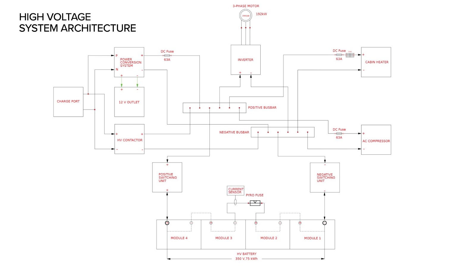
These are usually created with an electronic CAD. During the initial stages of design, block diagrams help conceptualize how different components within a system will interact. By representing components as blocks and their connections with arrows, engineers can brainstorm and explore various system configurations before diving into detailed design. This early visualization helps identify potential issues or inefficiencies early on, saving time and resources during later development phases.
Why block diagrams are used:
- Provides a high-level overview of the system, showing major components and their interconnections without detailed wiring
- Helps in understanding the overall system architecture and planning the wire harness design
Design Phase
Step 2: Electrical Schematics
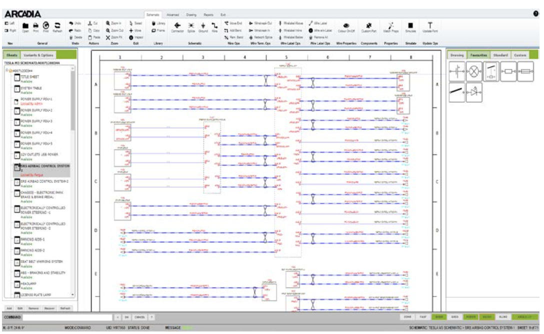
These types of electrical drawings serve as a crucial tool for designing, troubleshooting, and documenting electrical systems, ensuring everything functions as intended. Essentially, they depict the functional flow of electricity in a circuit.
Electrical schematics use standardized symbols for components like resistors, capacitors, and switches, focusing on how elements connect rather than the physical layout. Think of them as roadmaps highlighting which cities (components) are connected by highways (wires).
Electrical schematics are crucial for:
- Design and development of new electrical circuits
- Troubleshooting malfunctions by visualizing signal flow
- Understanding the overall functionality of a circuit
Tip: You can use electrical schematic software to make the design process easy. For example, cloud-based Arcadia Schematic for wire harnesses includes:
- Access to standard symbols and Intelligent library
- Real-time simulation
- Standard reports
- Integration with MCAD
Step 3: Harness Wiring Diagrams
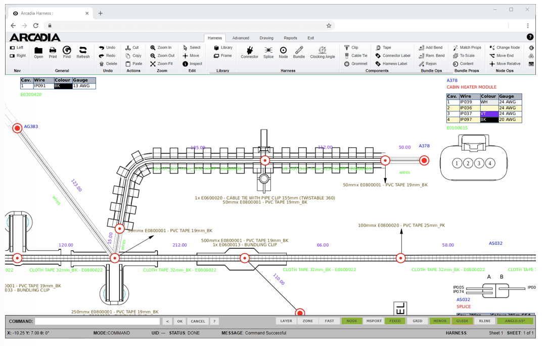
Electrical schematics and wiring diagrams are both essential tools for electrification, but they serve different purposes. While schematics focus on the functional connections between components, wiring diagrams bridge the gap between schematics and real-world installation. They depict the actual physical layout of wires and components within a machine.
Wiring diagrams provide crucial details, such as wire colors, sizes, splices, and connector types, ensuring the system is assembled and functions correctly. They also act as a step-by-step guide for electricians.
Wiring diagrams are essential for:
- Providing a visual representation of the entire electrical system, showing how components are interconnected
- Allowing for the early detection of design errors, such as incorrect connections, inadequate wire sizing, or missing components
- Verifying that the design will function as intended by mapping out the electrical paths
Tip: Arcadia Harness software makes your job easier:
- Generate harness from schematic
- Auto fetch the connector cavity parts
- Automatic selection of coverings and tubes
- BOM table and wire table
- Seamless synchronization between schematic and harness
- Easy switch between internal and manufacturing PN
- High-precision design rule checks
- Test scripts for harness testing
- Standard reports
- Integration with MCAD
Validation and Manufacturing Phase
Step 4: Formboards
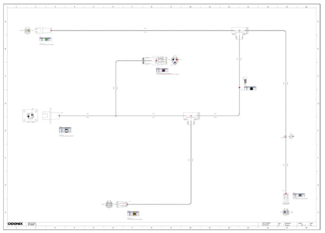
Formboards are blue-print types. During validation, formboards enable engineers to construct physical prototypes of wire harness layouts, allowing for meticulous testing and adjustment of design configurations. Using a 1:1 scale, this process ensures that the harness fits precisely within the intended space and functions as intended under real-world conditions. By simulating the actual installation environment, formboards help detect and rectify potential design flaws early in the development cycle, minimizing costly errors and ensuring optimal performance.
At the manufacturing stage, formboards provide a platform for detailed assembly layout and tooling setup, allowing manufacturers to streamline production workflows and maintain consistency in assembly procedures. Formboards are more than wiring diagrams, helping to align components accurately, verify assembly sequences, and ensure compliance with design specifications and quality standards.
Formboards provide:
- A life-size blueprint for efficiently building the electrical assembly
- Accuracy for wire length measurement and placement, minimizing the risk of errors
- Streamlined process for the production of complex wiring harnesses
Tip: Arcadia Formboard gives you these advanced features:
- One-click solution to generate a 1:1 harness
- Automated bend radius calculations
- Formboard Only BOM
- Streamline the production of complex harnesses.
- Detailed documentation for the shop floor
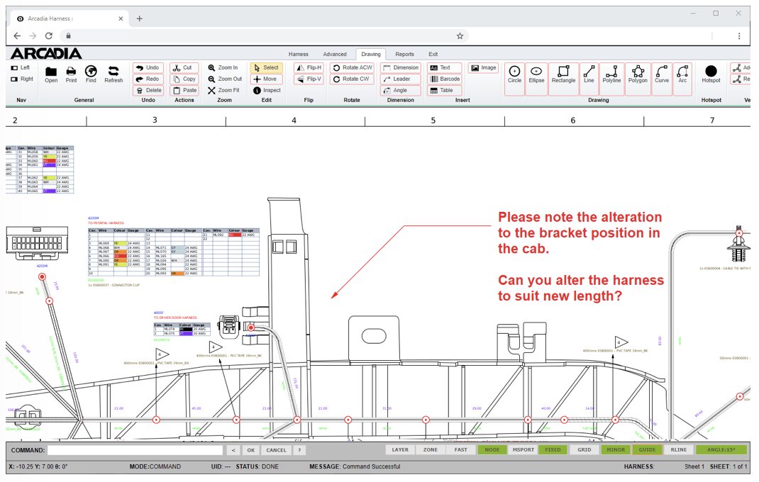
Upgrade Your Markup and Feedback System
Communication, collaboration, and review processes within product design and manufacturing are often riddled with inefficiencies.
Traditional methods such as paper markups and email exchanges usually lack clarity and can lead to missed or misinterpreted feedback during revisions. And not everyone involved will have access to the original design software, which hurts their ability to provide input or understand the design.
This lack of accessibility can create silos of information, making it difficult to get a holistic view of the project and leading to delays. Furthermore, real-time feedback on electrical schematics and wiring diagrams can be challenging with traditional methods, potentially causing misunderstandings and rework. The review processes themselves can be time-consuming, involving printing, marking up paper copies, and then re-entering feedback digitally, which is prone to errors.
These inefficiencies can create bottlenecks and lead to lost or overlooked information, ultimately impacting product quality, time-to-market, and overall project efficiency.
But there are cloud-based tools that can bring different departments and stakeholders together. Arcadia reView, for example, gives all relevant colleagues the ability to view and comment directly on the design data itself, using clear graphical and textual markups. This fosters real-time feedback, eliminates the need for paper trails, and ensures all input gets captured in one central location. With easy access for everyone involved, from engineers to customers, Arcadia reView promotes smoother collaboration and reduces the risk of missed improvements throughout the design and manufacturing lifecycle.
Ask us for a free demo
We’re happy to give you a free demonstration of our cloud-based electronic CAD solutions and other innovative software, so you can see the results for yourself. If you have any questions, we’re always happy to help.


